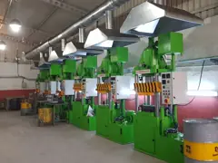
Mould layout
The arrangement and accessibility of multiple moulds determine the workspace design.

Your plan is empty.
Start by choosing a press solution.Explore hydraulic press models and current product options for your brake lining production process.

The 3D view is a representative model of the product family's form. Technical dimensions and equipment are determined by project requirements.
Model catalogue
Choose a model: the technical drawing and values update to it. Below, all models side by side.
| Specification | AHBP-250E-50 | AHBP-400E-50 |
|---|---|---|
| Pressing force | 100 – 250 ton | 100 – 400 ton |
| Operating pressure | 100 – 250 bar | 100 – 250 bar |
| Tooling area | 650 × 500 mm | 800 × 700 mm |
| Ram stroke | 500 mm | 500 mm |
| Maximum daylight | 600 mm | 600 mm |
| Approach speed | 100 – 200 mm/s | 100 – 200 mm/s |
| Working speed | 4 mm/s | 4 mm/s |
| Motor power | 7,5 – 11 kW | 15 kW |
HIDROSAY / PRODUCT REFERENCEThe arrangement and accessibility of multiple moulds determine the workspace design.
The mechanical arrangement is assessed to balance contact between the platen, mould and material.
Pressing, dwell and opening steps are sequenced according to process requirements.
Brake lining type, mould dimensions, material formulation, target cycle time and daily output.
Build your press